Based Lock with Keypad and LCD Display Circuit Diagram ð©ð¶ð±ð²ð¼ ðð²ðð°ð¿ð¶ð½ðð¶ð¼ð»:In this project, we will
PDF fundamentals of digital circuit and design Circuit Diagram Logic Gates: Logic gates are the
Make a Voice Controlled Robot 5 Steps with Pictures Circuit Diagram The Voice-Activated Personal Assistant
SMART SOLAR GARDEN LIGHT Circuit Diagram A variation of this project lets you solar power
How To Install Smart Light Switches Circuit Diagram Smart, Wi-Fi LED controllers turn any light
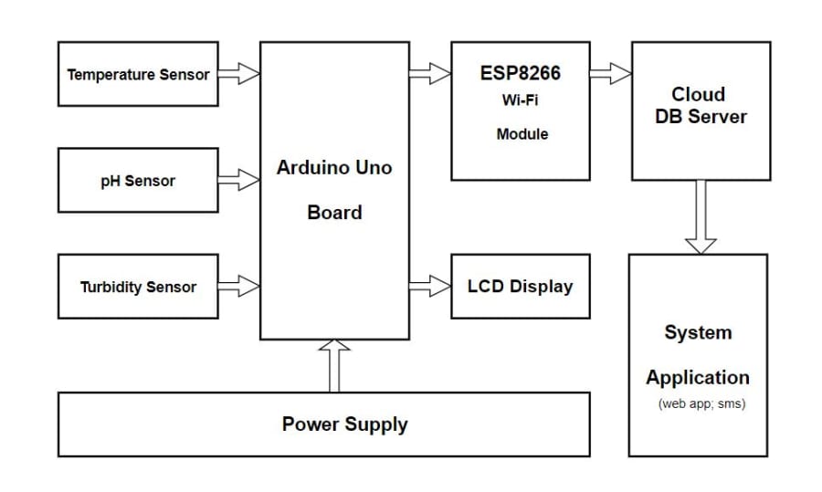
time Water Quality Monitoring System Circuit Diagram reconfigurable smart sensor interface device for water quality
Make An Arduino Based Automatic Fish Feeder The DIY Life Circuit Diagram Hello guys in
Instrumentation Amplifiers using Op Circuit Diagram Programmable gain signal amplification via the internal feedback resistor
Electronics Circuit Simulator Circuit Diagram Place and wire electronic components (even a lemon) to create
How to use a Breadboard TUTORIAL Circuit Diagram Learn how to connect components and power
14 of the best YouTube channels for electrical engineers Circuit Diagram Thanks for writing this
How To Make Amplifier Circuit At Home Wiring Draw And Schematic Circuit Diagram Build an
MAKE a HIGH VOLTAGE SUPPLY IN 5 MINUTES Circuit Diagram HIGH-VOLTAGE PCB DESIGN www.altium.com HIGH
transformer circuit diagram with explanation Key learnings: Three-phase Transformer Connections Definition: A three-phase transformer connects
Smart attendance system using face recognition Circuit Diagram We are building a Smart Attendance System
Final Design Schematic of Motor Control 11 Circuit Diagram Conclusion Understanding the different types of
battery management system circuit diagram This circuit measures the amount of current flowing in and
Exploring the Benefits of Frequency Counter Circuit Working and Circuit Diagram Techlogy 100mhz Frequency Meter.
Weather Monitoring And Forecasting Using IOT Circuit Diagram ð Project Description: This IoT-based Weather Monitoring
induction heating circuit diagram This diagram shows the addition of 2 diodes to the circuit